GPIO
This article goes over the basics of GPIO on the Raspberry Pi Pico.
GPIO stands for General Purpose Input and Output, and it refers a set of pins on the pico which we can interact with. These pins can either be read from (Input) or written to (Output).
“Writing to pins” means making certain pins supply a voltage or be a ground reference. This can be used to control simple components like LEDs and transistors.
“Reading pins” means seeing the state of a pin, to know if it’s connected to a voltage source or to ground. This is useful to gather information from the enviroment (through sensors) and to make interactive devices though buttons and switches.
Dependencies #
To be able to write to pins, we need to import OutputPin and InputPin from the Embedded HAL. The Embedded HAL (Hardware Abstraction Layer) provides generic features and functions microcontrollers usually have, and one of those is input and output.
The embedded_hal dependency should already be in the Cargo.toml, so OutputPin and InputPin can be imported normally:
use embedded_hal::digital::v2::{OutputPin, InputPin};
Output #
Defining an output pin is very straight forward. Right before the main loop, you can type something like this:
let mut whatever_name = pins.gpioXX.into_push_pull_output();
The name is just like with any other variable, you can call it whatever you want.
Note that there is also a mut. Since we’re going to be changing the state of the pin, it needs to be mutable.
Then from the pins struct, which contains all the pico’s pins we can use, we specifically take a gpio pin. Note that the XX are just a placeholder for a number, corresponding to the number of the GPIO pin you want to use. Lastly, we make that pin an output by calling into_push_pull_output().
The Embedded HAL also allows you to use into_readable_output(), which as the name implies lets you read the state of the pin. But that is rarely needed, so for the sake of simplicity we’ll just use a regular push_pull output. Push because when you want the pin to be a voltage source, it is “pushed” high, and Pull because it is “pulled” down when you want it to act like ground.
An example of how I would define an output pin is the following:
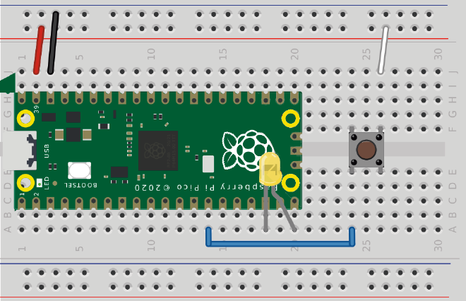
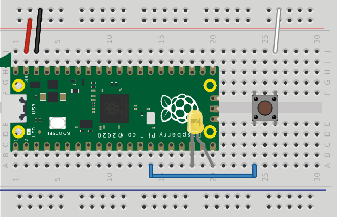
let mut yellow_led = pins.gpio15.into_push_pull_output();
Once a pin has been defined, you can go ahead an use it straight away. The simplest possible example is to make an LED blink:
loop {
    yellow_led.set_high().unwrap();
    delay.delay_ms(1000).unwrap();
    yellow_led.set_low().unwrap();
    delay.delay_ms(1000).unwrap();
}
To make the a GPIO pin supply a voltage, we have to call set_high() on it. That will make the LED turn on. And to turn it off we’ll make the pin a ground with set_low(). Notice how both after set_high() and set_low(), unwrap() is called. That is because both of those functions return a Result enum, which has to be taken care of.
You can also see we used the delay struct. In order for the LED to stay on and off for whatever period of time we want, we have to tell the pico to wait before it continues to the next instruction.
To do that, we can call delay_ms() to wait a set amount of milliseconds. (1 second is 1000 milliseconds)
And that’s pretty much all there is to the Output! It’s just making pins high or low.
Input #
Defining an input pin is very similar to defining and output one.
let whatever_name = pins.gpioXX.into_XXXXX_output();
Since we can only read an input, not modify it, adding mut is not necessary.
Just as with the Input, the XX after gpio is a placeholder for a GPIO pin number.
But as you can see, there’s another placeholder after. This is because there are different types of input:
pull_downmakes it so the pin is connected to ground through a resistor on the pico. This means the pin is low by default, and if we want to change it’s state we have to connect it to a voltage source.pull_upmakes it so the pin is connected to 3.3V through a resistor on the pico. This means the pin is high by default, and if we want to change it’s state we have to connect it to ground.floatingmakes it so the pin is neither connected to 3.3V or ground. This means you have to use your own pullup or pulldown resistor for your readings to be stable.
The following example uses a pulldown input to read a button, which is going to be used to determine if an LED should be on or off.
let mut yellow_led = pins.gpio15.into_push_pull_output();
let button = pins.gpio10.into_pull_down_input();

loop {
    if button.is_high().unwrap() {
        yellow_led.set_high().unwrap();
    } else {
        yellow_led.set_low().unwrap();
    }
}
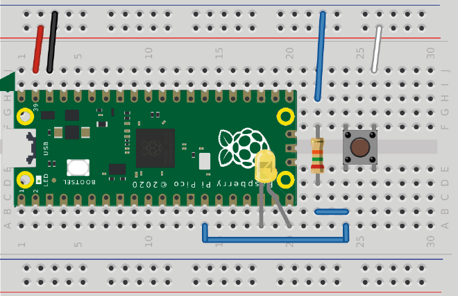
The circuit looks like this:

If we look at the circuit, we’ll see that when the button is pressed, the GPIO pin 10 will be connected to VSYS, making it high. To check if a pin is high, we can call .is_high().unwrap() on it. This returns either true of false, depending on if the pin is high or not, respectively.
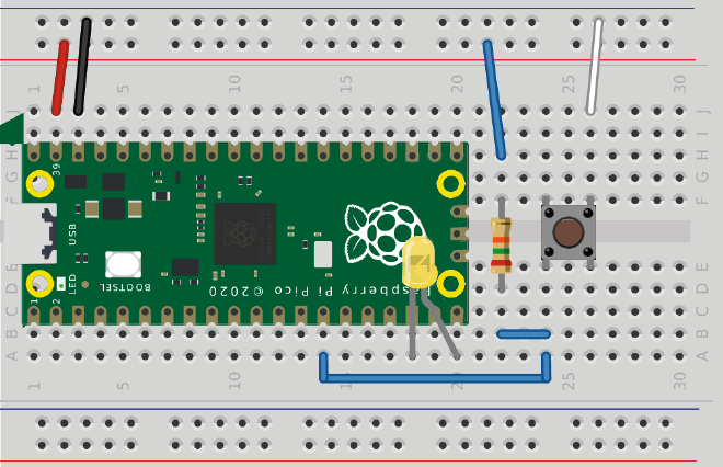
If you wanted to make the exact same program but connecting the button to ground instead like in this circuit

You will have to use a pull_up input.
let mut yellow_led = pins.gpio15.into_push_pull_output();
let button = pins.gpio10.into_pull_up_input();

loop {
    if button.is_low().unwrap() {
        yellow_led.set_high().unwrap();
    } else {
        yellow_led.set_low().unwrap();
    }
}
Notice how the logic has changed. Since a pullup input will make it so the pin is high by default, we have to make the logic do the opposite. This is why we use is_low().unwrap(). is_low will be true when the pin is connected to ground, which is exactly what will happen when the button is pressed.
Lastly, to use a floating input you’ll have to add your own pullup or pulldown resistors


.into_floating_input() on the button definition like this:
let button = pins.gpio10.into_floating_input();